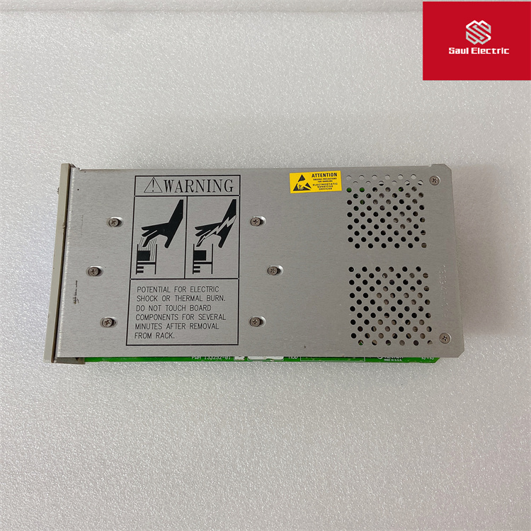
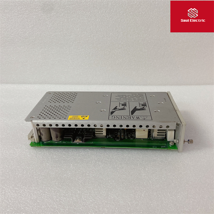
350015 133292-01BENTLY 低压直流模块
Bently 3300 Overview of the system
Working principle
Instrument measurement adopts the principle of approaching eddy current. The probe is composed of a coil with a high frequency signal. When the metal surface of the measured shaft changes relative position with the probe, the size of the eddy current formed changes, so that the energy loss of the high frequency signal in the probe changes. The change signal is converted into a voltage signal corresponding to the voltage of the gap measured by the probe through the preprocessor, and the signal enters the monitor in the component box. Display as a reading after conversion inside the monitor. Structure of the Bentley 3300 system loop
The system consists of a 3300 series instrument assembly box with a corresponding preamplifier and a sensor (probe) with cable. Each parameter is measured by the probe preprocessor and the monitor together.
The main calibration instruments include Bentley TK3-2E calibrator, 4-digit semi-digital voltmeter, 24V DC regulated power supply and function generator.
Calibration of sensor
Connect the probe with the extension cable, and the other end of the extension cable is connected to the preprocessor. The power end of the preprocessor (-24VDC) and the common end (com) are connected to the -24VDC power supply, and the common end and the output end are connected to the digital voltmeter.
The probe is fixed on the probe seat with a suitable probe clamp so that the tip of the probe is in contact with the calibration target.
Send -24VDC to the power and common ends of the preprocessor, then adjust the screw micrometer on the TK3-2E calibrator so that the indicator is at 0mm, then increase the indicator value of the micrometer to 0.25mm and record the voltage value of the digital voltmeter (which is the output voltage of the preprocessor). Increase the gap at 0.25mm each time until the indicated value is 2.5mm, and record the output voltage value each time (check point no less than 10 points). According to the recorded data, according to the form of the calibration curve of the axial displacement sensor, the gap voltage curve of the calibrated probe sensor system is drawn, which reflects the characteristics of the sensor. According to the drawn gap - voltage curve, determine the linear range of the sensor system, should not be less than 2mm. The sensitivity of the sensor system is calculated to be 7.874V/mm, and the nonlinear deviation in the linear range is no more than 20um. Voltage increment divided by gap increment is sensitivity. The linear center of the sensor is the static setting of the axial displacement sensor. The calibration method of the vibration sensor is the same as that of the data recording coaxial displacement sensor. The gap voltage curve should also be drawn to calculate the sensitivity of the sensor system. The error of the sensor system is not more than ±5% within the linear range of 2mm. The linear center of the sensor is the installation reference point of the shaft vibration sensor.
主要功能:BentlyNevada机械状态监测
详细参数描述
3500/32M4通道继电器模块提供四个继电器输出和高度可配置的继电器逻辑接口。
四个输出中的每一个都可以独立编程,以通过为每个继电器配置警报驱动逻辑来启用投票。
3500机械保护系统内的所有通道都可用于使用NotOK状态以及3500/32M内的警报和危险设置点来驱动复杂逻辑。
3500/32M为高度可配置的AND/OR逻辑组合提供易于使用的界面,包括“正常”和“真”和表决选项以及闭锁继电器通道选项。
4通道继电器模块是一个全高模块提供四个继电器输出。任何数量的4通道继电器
模块可以放置在瞬态数据接口模块。
4的每个输出-通道继电器模块可独立编程为执行投票逻辑。
4通道继电器模块上使用的每个继电器包括
报警驱动逻辑。
报警驱动逻辑的编程使用AND和OR逻辑,
并且可以使用报警输入(警报和危险状态),
不正常,或来自任何监视器通道或任何
机架中监视器通道的组合。你可以
编程此报警驱动器以满足您的应用需求
使用3500机架配置软件。
BENTLY本特利3500/32M继电器模块4通道应用广泛,例如工厂是否发电、压缩和泵送工业所依赖的流体或驱动工艺设备关键机械每天每小时一次。
在这些设置,机械故障不仅不方便,还可能灾难性的尽管仅维修成本就可能令人震惊,
由于以下原因造成的部分甚至全部生产损失,关键机械故障–有时价值数百万日–可以表示损益之间的差异整个一年。
有这么多危险,机械状态监测不仅仅是一个好主意,它是一个必然性持续监控关键资产参数,如振动、温度、速度和许多其他条件指标是一种行之有效的预测和预防方法
全国服务热线
18030183032
邮 箱:3248602330@qq.com
地 址:厦门市思明区吕岭路1733号创想中心2009-2010单元

Copyright © 2022-2024 厦门雄霸电子商务有限公司 版权所有 备案号:闽ICP备14012685号-38


18030183032