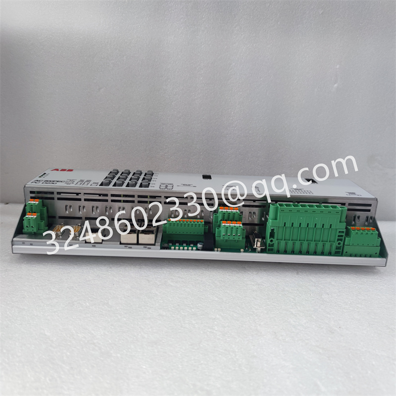
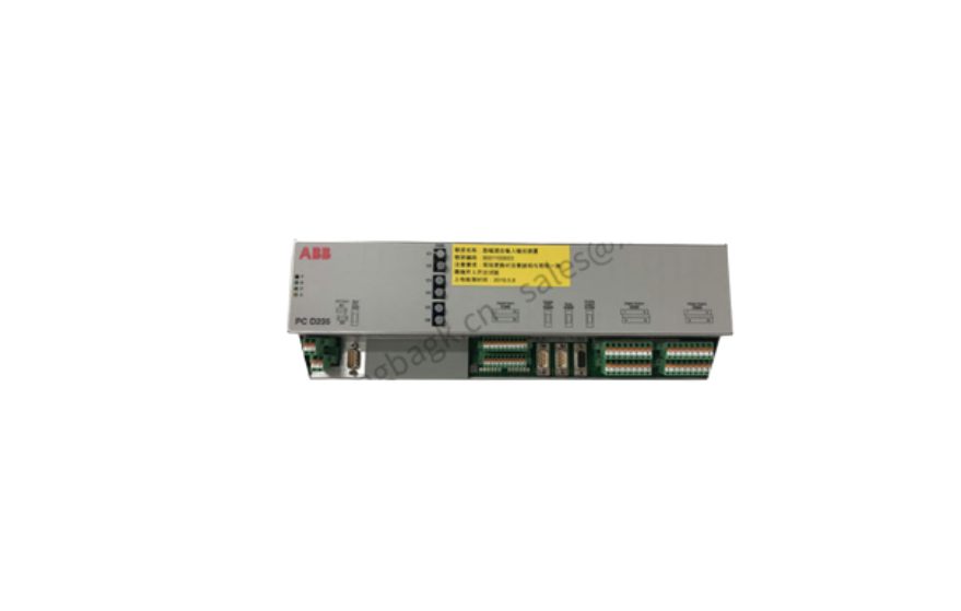
ABB PCD235A101 3BHE032025R0101 励磁控制系统控制器
励磁装置主回路部分主回路的组成和功能
装置主回路完成整流和灭磁两大功能,系统采用三相全控桥可控硅整流电路,向同步电动机转子绕组提供直流励磁电流。灭磁回路由可控硅7、
8KGZ与二极管GZ反并联组成,实际上组成为一个大功率电子开关,完成同步电动机在异步起动过程中串入起动电阻,起动结束后自动切除,保证同步电动机在异步起动期间,转子励磁绕组既不开路也不短路,从而避免励磁绕组承受过电压和过电流。
励磁装置控制部分:
系统控制部分包括S720OPLC、Pro-face触摸屏、KGLF-2型微机励磁控制器三部分组成。PLC主要完成继电回路逻辑控制工作方式切换、运行时PI调节以及对外通讯等工作,Pro-face触摸屏主要完成系统参数设置和运行时故障、工作时间、设定运行参数信息查询,Pro-face触摸屏具有励磁电流和励磁电压录波曲线信息查看。
KGLF-2型励磁控制器里由主机MC87C51和副机AT89C51单片机组成。励磁控制器主要完成频率测量及投励、脉冲形成、故障检测及处理。1转子感应电压频率的测量
同步电动机起动时,转子感应电压的频率随着转速的上升逐渐下降同步电动机一旦起动,单片机就立即检测转子感应半个周波的时间, 从20ms开始,数码管记“9”中间每增加20ms,数码减1,到20Oms时数码管显示“0”。同步电动机在异步起动过程中,当转子转速达到同步转速的90%时,转子感应电压的频率SHz,周期0.2s,半周时间为100ms,计算机一旦检测到该值,立即投全压。投全压后,电动机的转速将继续上升,当转速增加到同步转速的95%时,转子感应电压的频率为2.5Hz,周期为0.4s,半周时间为200ms,计算机检测到此值,迅速进入整流程序,输出脉冲,装置投入励磁同时接通投励工作指示,关掉低压灭磁并开放失磁保护和失步保护等。
2脉冲形成
同步信号Ta、W3提供正偏移,及励磁调节器的输出信号Uk,三者通过运算放大器综合处理后作为单片机外部中断请求INTO的输入信号,当INTO从1变0时,单片机接受中断,立即发出第一组脉冲去触发1#可控硅,同时给6#可控硅补一个脉冲。以后每间隔60°发下一组脉中,触发相应的可控硅直至一个周期六组脉冲发完,再等待下一次中断。改变Uk的大小就改变了中断申请的时刻,达到控制口角的目的。为了提高整流电压波形的对称度,系统还不断监测电网的频率,随时对60°定时进行修正,确保整流电压波形对称,这样产生的脉:冲精度高,无需外部调整,且稳定可靠。
3故障保护
系统具有进线电源空开跳闸、电源掉相、快熔熔断、欠磁、失步、过流、起动超时等保护。这些故障主要由辅机监控检测,一旦确认故障发生,辅机立即通知主控计算机,主机接收此信号后迅速作出相应的故障处理,发出故障显示和声响信号,接通高压油断路器分闱回路,同步电动机紧急停车。同时系统推β逆变运行,将励磁绕组储存的能量回馈电网,延时5~6s后封锁脉冲。
故障发生后由辅机记忆故障原因,并显示故障代码,以便查询处理。
The composition and function of the main circuit of the excitation device
The main circuit of the device performs two functions of rectification and demagnetization. The system adopts three-phase fully controlled bridge thyristor rectifier circuit to provide DC excitation current to the rotor winding of synchronous motor. Magnetic circuit by thyristor 7,
8KGZ and diode GZ anti-parallel composition, in fact, composed of a high-power electronic switch, complete synchronous motor in the asynchronous starting process into the starting resistance, automatic cutting after the end of the start, to ensure that synchronous motor during the asynchronous start, the rotor excitation winding neither open nor short circuit, so as to avoid the field winding to withstand overvoltage and overcurrent.
Excitation device control part:
The control part of the system consists of S720OPLC, Pro-face touch screen and KGLF-2 microcomputer excitation controller. PLC mainly completes the switching of relay circuit logic control working mode, PI adjustment during operation and external communication, etc. Pro-face touch screen mainly completes the system parameter setting and operation fault, working time, set operation parameter information query, Pro-face touch screen has the excitation current and excitation voltage recording curve information view.
KGLF-2 excitation controller is composed of MC87C51 and AT89C51 microcontroller. Excitation controller mainly completes frequency measurement and excitation, pulse formation, fault detection and processing. 1 Measurement of rotor induced voltage frequency
When the synchronous motor starts, the frequency of the rotor induced voltage gradually decreases with the rise of the speed. Once the synchronous motor starts, the MCU immediately detects the rotor induced half cycle time. From 20ms, the digital tube marks the middle of "9" every 20ms, the number decreases by 1, and the digital tube displays "0" when it reaches 20Oms. Synchronous motor in the asynchronous starting process, when the rotor speed reaches 90% of the synchronous speed, the rotor induced voltage frequency SHz, period 0.2s, half week time is 100ms, once the computer detects the value, immediately throw full voltage. After full voltage, the motor speed will continue to rise. When the speed increases to 95% of the synchronous speed, the rotor induced voltage frequency is 2.5Hz, the period is 0.4s, and the half cycle time is 200ms, which is detected by the computer. Quickly enter the rectification program, output the pulse, the device is put into the excitation at the same time turn on the excitation work instruction, turn off the low voltage magnetic field and open the loss of magnetic protection and out-of-step protection.
2 Pulse formation
The synchronization signals Ta and W3 provide positive offset and the output signal Uk of the excitation regulator. After comprehensive processing by the operational amplifier, the three signals are used as the input signals of the external interrupt request INTO of the single chip microcomputer. When the INTO changes from 1 to 0, the single chip microcomputer accepts the interrupt and immediately sends out the first set of pulses to trigger the 1# thyristor, and at the same time, a pulse is added to the 6# thyristor. After every 60° interval in the next set of pulses, trigger the corresponding thyristor until a cycle of six sets of pulses are completed, and then wait for the next interruption. Changing the size of the Uk changes the time at which a request can be interrupted, in order to control squabbles. In order to improve the symmetry of the rectifier voltage waveform, the system also continuously monitors the frequency of the power grid, and corrects the 60° timing at any time to ensure that the rectifier voltage waveform is symmetrical, so that the pulse generated: high impact accuracy, no external adjustment, and stable and reliable.
3 Fault Protection
The system has the protection of incoming power circuit breaker trip, power phase drop, fast melting, under-magnetization, out-of-step, overcurrent, starting timeout, etc. These faults are mainly monitored and detected by the auxiliary machine, once the fault is confirmed, the auxiliary machine immediately notifies the main control computer, the host receives this signal and quickly makes the corresponding fault treatment, issues the fault display and sound signal, connects the high pressure oil circuit breaker division circuit, and the synchronous motor stops in an emergency. At the same time, the system pushes β inverter operation, the energy stored in the excitation winding is returned to the grid, and the pulse is blocked after a delay of 5~6s.
After the fault occurs, the auxiliary machine remembers the cause of the fault, and displays the fault code for query and processing.

*更多关干我们公司的信息
我们大量的工业产品库存已准备好发货,这是我们产品的核心。它包含更多超过400,000种电子产品,如PLC,HMI,驱动器,伺服和CNC设备,IPC和PG.
无论是新的还是停产的,从最小的模块到完整的配置。我们有多年的产品不容易获得,最新技术和介于两者之间的所有其他产品。
对市场的洞察力、技术发展和客户需求使我们能够战略性地购买,所以我们很少需要转移我们的业务。如果商品碰巧缺货,我们将搜索我们的首选供应商网络。
*您可能需要的某些零件:07AI91 ABB模拟输入输出模块
SCHROFF MPSO22 13100-203
CTI250O-RBC 901E-250O-RBC
B&R 5AP1130.156C-000
NI GPIB-14OA/2
GE IC695CPU315-BB
ABB CI570 3BSE001440R1
ABSOLUTE API4380-G
FOXBORO FBM230 P0926GU
EMERSON 1C31203G01
ALSTOM V4561983-0100 V4559856
FOXBORO FBM233 PO926GX
ENTERASYS A4H124-24TX PO973JM
HIMA F8650x 984865065
HIMA X-FAN1003 993201013
SCHUMACHER ATCS-15 1464-0320
ABSOLUTE API4380G
HIMA LMO02_MAX 985020002
FOXBORO FBM230 P0926GU
KROHNR OPTIFLUX4300W IFC300w
HIMAX-DI1601 985210222
GE F650-N-F-L-F-2-G-1-HI-P-6E
PROSOFT PTQ-PDPMV1
HIMAX-BLKO1 632590802
Sartorius MDB-8E
*免责声明:
雄霸销售工业自动化零件,包括新产品和停产产品,以及购买此类特色产品通过独立渠道进行。雄霸不是授权经销商,本网站上特色产品的经销商或代表。
所有产品名称/产品图片,本网站上使用的商标、品牌和徽标是其各自所有者的财产。
带有这些名称、图像、商标、品牌和徽标的产品描述、描述或销售仅用于识别目的,并不意味着与任何权利持有人有任何从属关系或授权。
全国服务热线
18030183032
邮 箱:3248602330@qq.com
地 址:厦门市思明区吕岭路1733号创想中心2009-2010单元

Copyright © 2022-2024 厦门雄霸电子商务有限公司 版权所有 备案号:闽ICP备14012685号-38


18030183032