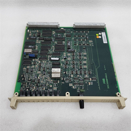
KOLLMORGEN TT-4501-1000-3
KOLLMORGEN TT-4501-1000-3
KOLLMORGEN TT-4501-1000-3
KOLLMORGEN 64WKS系列控制器64WKS-M240/50-RLG、64WKS-M240/50RL、64WKS-M240/70、64WKS-M240/50、64WKS-M240/70PB、64WKS-M240/50KP、64WKS-M240/50-R、64WKS-M240/70-RLGKOLLMORGEN 64WKS系列控制器64WKS-M240/50-RLG64WKS-M240/50RL、64WKS-M240/70、64WKS-M240/50、64WKS-M240/70PB、64WKS-M240/50KP、64WKS-M240/50-R、64WKS-M240/70-RLGKOLLMORGEN 64WKS系列控制器
大量供应DCS系统的配件,PLC系统的配件。
主营:本特利,英维思,伍德沃德,福克斯波罗、西屋、瑞恩、施耐德莫迪康、ABB、AB、西门子、摩托罗拉、GE发那科、安川、博世力士乐,ACSO,YOKOGAWA横河,力士乐等各的DCS系统配件,机器人系统配件,大型伺服系统备件
工控产品基本上都有,无法找到的商品可以联系客服帮您查询的PLC 、DCS 系统备件 模块
Allen-Bradley(美国AB)系列产品》
Schneider(施耐德电气)系列产品》
General electric(通用电气)系列产品》
Westinghouse(美国西屋)系列产品》
销售ABB Robots. FANUC Robots、YASKAWA Robots、KUKA Robots、Mitsubishi Robots、OTC Robots、Panasonic Robots、MOTOMAN Robots。
estinghouse(西屋): OVATION系统、WDPF系统、MAX1000系统备件。
Invensys Foxboro(福克斯波罗):I/A Series系统,FBM(现场输入/输出模块)顺序控制、梯形 逻辑控制、事故追忆处理、数模转换、输入/输出信号处理、数据通信及处理等。Invensys Triconex: 冗余容错控制系统、基于三重模件冗余(TMR)结构的zui现代化的容错控制器。
◆Motorola(摩托罗拉):MVME 162、MVME 167、MVME1772、MVME177等系列。
Foxboro(福克斯波罗):I/A Series系统,FBM全系列(现场输入/输出模块)
顺序控制、梯形逻辑控制、事故追忆处理、数模转换、输入/输出信号处理、
数据通信及处理等。
Westinghouse(西屋):1C31系列DCS系统、CPU、OVATION系统、WDPF系统、
WEStation系统备件。
Triconex(英维思):冗余容错控制系统、基于三重模件冗余(TMR)结构的现代化的容错控制器。
EMERSON(艾默生):模块、卡件、驱动器等各类备件。
ABB:PM全系列DCS系统、IGCT高压变频器系列、工业机器人备件DSQC系列、INFI 90等。
Bailey(贝利):BRC系列DCS系统等。
Allen-Bradley:1756、1785、1771、1746全系列系统等。
Yokogawa(横河):CP系列等。
Honeywell(霍尼韦尔):TK/TC/CC系统等。
Reliance(瑞恩):57C系列等。
Schneider(施耐德):140系列处理器、控制卡、电源模块等。
Modicon(莫迪康):AS系列PLC系统备件。
Siemens MOORE,Siemens Simatic C1,Siemens数控系统等。
Motorola(摩托罗拉):MVME 162、MVME 167、MVME1772、MVME177等系列。
XYCOM:I/O、VME板和处理器等。
GE(通用电气):IC698/IC697全系列PLC系统、模块、卡件、驱动器等各类备件。
"Device independence" in the pump control configuration engineering with the help of timer and script strategy, initially realized the pump control system simulation operation, did not achieve the purpose of real-time monitoring, so the next monitoring Settings.
As we know, the pump operation control is mainly controlled by PLC, and the MCGS system, on the one hand, need to collect relevant data from PLC, change the value of the corresponding variable in the real-time database, and then show the animation form of the graph component in the picture, so as to achieve the purpose of monitoring operation; On the other hand, it is also necessary to write the pause and running time set in the upper setting environment into the PLC to realize the adjustment of the running time of the pump, as well as the operation and stop control of the pump hardware system through the start and stop buttons of the upper computer.
Open the previous "Task one" and save it as "Pump Operation Monitoring" to improve the project animation and property setting of "Task One" configuration.
(1) Delete the timer policy and script policy. When online, PLC completes the control task, so configuration engineering
The timer and script in the
(2) Modify the four data objects related to timer in the database, namely "timer start", "timer reset", timing time and time arrival, to improve the efficiency of the operating environment. Then four new data objects are added, namely "Run time Display", "Run Time Adjustment", "Pause Time Display" and "Pause Time Adjustment". The object types are numeric.
(3) Delete the symbols related to timer in the "Animation Configuration Pump Control" window, and make 6 new text labels.
(4) Make an animation window as shown in the picture.
In the device window, add a Common Serial port parent device and a Siemen_S7200PPI.
(5) After the selection, set the attributes of the device so as to communicate with MCGS.
(6) Set serial port terminal number to COM1. Set data verification mode to Parity and collection data to Synchronous Collection. The minimum collection period is set to 200ms. [Set according to the PLC model connected]
(7) Set the Siemens PPI attribute and add 4 i registers, 2 Q registers, 3 M registers and 4 VW registers.
(8) First draw the PLC program on the drawing, pay attention to the correct control configuration, so in the process of program design to carry out data conversion. Add the transfer instruction and integer division instruction, and put the timer time divided by 10 into the register. Also add "upper computer start" and "Upper computer stop".
(9) In the online monitoring operation, it is necessary to close the Step7 software when opening MCGS, and then connect the channel, until the display is 0, it means that the connection is successful, then the monitoring test can be carried out.
Task three manipulator control system
The operation control of manipulator is more difficult than the first two tasks.
(1) First, we will create a project named "Manipulator Operation Control", and then create a new window in the user window named "Manipulator Control".
(2) Create the required symbols in the user window.
A. Create four buttons named Start, Reset, Timer Start, and timer reset.
B. Use labels to create 2 text boxes named, Time, and Time, and 4 rectangular boxes respectively.
C. A rectangular frame is used to establish the base of the manipulator, and a pipe is used to establish the cross arm and vertical arm of the manipulator, and then three rectangles are used to establish the gripper.
D. Add six identical step indicators and two start and reset indicators. Six of the steps are down, tight, up, left, right and relax.
E. As for the blocks to be moved, of course you have to draw them yourself. Use a rectangle and two ovals to form a whole by changing fill colors and composing symbols.
(3) Add switch data in real-time database, which are timer start, timer reset, start, reset, down clamp, up, right shift, relax and left shift respectively. Left and right artifacts.
(4) Add data such as vertical movement amount, horizontal movement amount, timing time and time to.
(5) Add related attributes to each symbol. Note that the two rectangles connecting the pipe should be combined symbols because the "amount of horizontal movement" attribute should be added.
(6) After the relevant attributes are selected from the real-time strategy in the expression, the properties of size change should be added to the mechanical arm at last. The calculation method is that the total length of the arm after extension = the actual length of the arm + the amount of extension. How to measure the length, draw a straight line first and open the status bar in the view bar, and the length will be displayed in the lower right corner.
(7) The value of the expression in the property box is divided by the time of decline by 200ms
(8) Add scripts and timers to the loop policy.
Task four manipulator operation monitoring
The practical implications of monitoring have been covered in Task 2, so it is not covered in detail in this task.
(1) Delete the timer policy and script policy. [When online, PLC completes the control task, so the timer and script program in configuration engineering are useless] Modify the four data objects related to timer in the database, respectively "timer start", "timer reset" timing time and time to improve the efficiency of the operation environment. Then four new data objects are added, namely "Run time Display", "Run Time Adjustment", "Pause Time Display" and "Pause Time Adjustment". The object types are numeric.
(2) Delete the symbols related to timer in the "Manipulator Operation Control" window.
(3) Make an animation window as shown in the picture.
(4) In the device window, add a Common Serial port parent device and a Siemen_S7200PPI.
(5) After the selection, set the attributes of the device so as to communicate with MCGS.
(6) Set serial port terminal number to COM1. Set data verification mode to Parity and collection data to Synchronous Collection. The minimum collection period is set to 200ms. [Set according to the PLC model connected]
(7) Set the properties of Siemens PPI, add 4 i registers, 14 Q registers and 6 M registers to the basic properties, in which M2.0 is the start of the upper computer and M2.1 is the stop of the upper computer.
(8) First draw the PLC program on the drawing, pay attention to the correct control configuration, so in the process of program design to carry out data conversion. Add the transfer instruction and integer division instruction, and put the timer time divided by 10 into the register. Also add "upper computer start" and "Upper computer stop".
(9) In the online monitoring operation, it is necessary to close the Step7 software when opening MCGS, and then connect the channel, until the display is 0, it means that the connection is successful, then the monitoring test can be carried out.
64WKS-M240/70、
64WKS-M240/50、
64WKS-M240/70PB、
64WKS-M240/50KP、
64WKS-M240/50-R、
64WKS-M240/70-RLG、
KOLLMORGEN 64WKS系列控制器
64WKS-M240/50-RLG、
64WKS-M240/50RL、
64WKS-M240/70、
64WKS-M240/50、
64WKS-M240/70PB、
64WKS-M240/50KP、
64WKS-M240/50-R、
64WKS-M240/70-RLG、
AKM54K-ANC2AB01
AKM54K-ANCNR-00
AKM54L-ANCNR-00
AKM54L-CSSNR-02
AKM63G-ACSNR-02
AKM63M-ANCNDA-00
AKM63M-ANCR-00
AKM63N-ACC2R-00
AKM65M-ACCNR-00
AKM73Q-ANCNR-00
AKM74P-ACCNR-00
TT-2931-1010-AG
TT2931-1011-AA
TT-29500-3146-C
TT-2950-3055-R
TT-2952-4051-A
TT-29530-3145-A
TT29533058A
TT2953-4011-B
TT-4205-4017-C
TT-4207-4019-D
TT-4287-1010-D
TT-4500-1010-B
TT-4501-1000-3
TT-2043-1011-B
TT-2045-3026-A
AKM43E-ANSNS-06
S20330-SRS
6SM37L-4.000
全国服务热线
18030183032
邮 箱:3248602330@qq.com
地 址:厦门市思明区吕岭路1733号创想中心2009-2010单元

Copyright © 2022-2024 厦门雄霸电子商务有限公司 版权所有 备案号:闽ICP备14012685号-38


18030183032